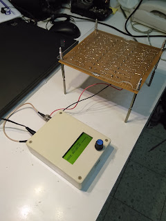
I will not describe my process here, but my reference is a set of amazing videos by Dmitry Dementiev:
https://www.youtube.com/watch?v=hKJiR35kjpI
https://www.youtube.com/watch?v=El_O8IMgWUk
https://www.youtube.com/watch?v=yPS-ldzMQRI
It is all in Russian. There are similar English videos on youtube, but I followed Dimitry's since he describes things really well. If you don't understand Russian and still want to know how to do it - let me know, I will try to do some translation.
Anyway, here is my first home made PCB.
 |
| UV-Timer PCB immediately after etching |
 |
| UV-Timer PCB with photoresist removed |
It is a modified version of Dmitry's timer for UV LED lamp.
Here is my schematics:
There are few changes compared with Dmitry's schematic:
- I have put another MOSFET and controlling resistors
- I removed controlling buttons. All control is done from rotary encoder
- I have wrote the firmware from scratch. Just for fun.
All the code and schematics are at https://github.com/kloper/uv-timer
A few more photos of the timer being built:
 |
| Board fully populated |
 |
| Bottom side with a few patches for a first version (fixed on github) |
 |
| Fully populated board |
 |
| Very first working version of firmware |


No comments:
Post a Comment