Intro
I am continuing working on the digital thermometer based on STM32F030. Here is my current setup:
I have put almost everything on a prototype board since Vdd on breadboard was too unstable for ADC measurements. Thermistor is on the breadboard. The whole thing is stable and shows true ambient temperature. But this is a subject for another blog.
Right now I want to describe HD44780 connection.
Hitachi HD44780
HD44780 is a whole family of LCD displays based on Hitachi HD44780. They are cheap, require only 7 (8 if terminal reset is required) control wires from MCU and provide enough space to show a little textual information. Just enough for most small DIY projects. The one on the picture I have bought on local junk yard for 10NIS.
Additionally, they are relatively low power. The whole circuit on the picture draws 40mA with 5V input.
There are lots of guides and libraries about HD44780 on the internet. I just recommend trying to read the HD44780 datasheet (link from Wikipedia). Boring as hell, sometimes obscure, but absolutely required if you want to understand full capabilities of the display.
Wiring
Most HD44780 compatible displays have the same set of 16 physical connections. Here is snip for my CCM2040 datasheet:

With display enabled, it automatically shows content of the Display Data RAM (DDRAM). The DDRAM is 80 characters long with first address 0 and last address 79. The complication is how the physical display lines are mapped onto that address space.
I will try explain by example:
void hd44780_putchar(char c) {
hd44780_dr_write(c);
hd44780_wait_busy();
}
void hd44780_puts(const char * str, int size) {
for (int i = 0; i < size; i++)
hd44780_putchar(str[i]);
}
void hd44780_goto_addr(uint8_t addr) {
hd44780_ir_write(HD44780_CMD_SET_DDRAM_ADDR | addr);
hd44780_wait_busy();
}
Now it is easy, just call hd44780_goto_addr(0) to make current DDRAM address register in the controller to point at address 0 and then run something like hd44780_puts(buffer, strlen(buffer)) in order to display the text on the first line.
To go to the second line just run hd44780_goto_addr(40).

The first two pins are for ground and controller power supply. The last two pins are same but for the back-light.
Pin 3 is for contrast control. For prototyping I often ground it to get maximum contrast, but normally it should be connected via trimmer to get adjustable voltage between ground and Vdd.
Pin 4 is Register Select. It instructs HD44780 controller to use Data (HIGH) or Instruction (LOW) register. Using Data Register allows to alter controller's memory (either text displayed or font memory). Using Instruction Register allows to alter display settings, clear display, move cursor, etc...
Pin 5 is Read/Write. It instructs HD44780 to perform either Read (HIGH) or Write (LOW). Combined with Register Select this pin controls reading/writing from Data/Instruction registers.
Pin 6 is Enable Operation. HD44780 will start sampling values on other pins when Enable Operation goes HIGH and latch those values when it goes LOW.
Pins 7-14 are Data Bus. HD44780 can operate in two modes. In 8-bit mode it will treat all Data Bus bits. In 4-bit mode pins 7-10 are not used and communication is done via pins 11-14 by sending a single byte nibble after nibble.
A huge disadvantage of the 8-bit mode is the extra four pins that must be connected to MCU. For MCUs with low pin count 8-bit is just too much. Thus, I am using 4-bit mode.
But if you have enogh GPIO ports 8-bit mode has two advantages:
- It is a little bit simpler to implement in software. For example display reset routine need not to have code for switching to 4-bit mode
- It is a little bit faster since there is no need to send data/control byte by nibbles
In order to communicate with the display the RS, RW, EN and DB4-7 wires should be connected to GPIO ports on MCU. The MCU will then do a little bit banging in order to drive the display.
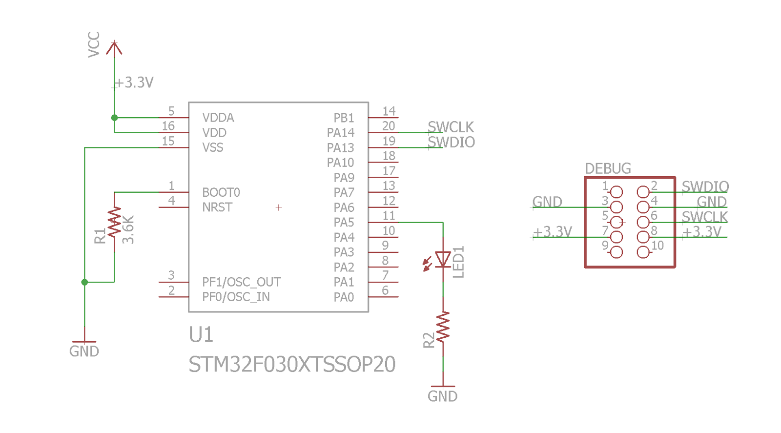
I also like to be able to turn the display off, for reset and power saving purposes. Thus, one extra wire is used as a control signal for turning the display on and off. Here my current schematics:
 As you may see all control lines except the display rest are connected to GPIO port A. This is not a must but simplifies the driver code.
I am not going into deep details of the display protocol. For now I will put here a list of routines that are needed to make a simplest HD44780 4-bit mode display driver.
I also like to be able to turn the display off, for reset and power saving purposes. Thus, one extra wire is used as a control signal for turning the display on and off. Here my current schematics:

Implementing minimal driver
I have ported my own code from HD44780 display driver for atmega368 family to STM32F030. The code is available on Github, not a perfect state, but does work and quite stable.I am not going into deep details of the display protocol. For now I will put here a list of routines that are needed to make a simplest HD44780 4-bit mode display driver.
- nibble_out - accepts 4-bit value to be sent to display via DB4-DB7 pins.
- Set EN HIGH
- Set values on GPIO lines leading to DB4-DB7 to the nib value
- Wait a couple of clocks for the values on GPIO to stabilize, just to be sure
- Set EN LOW
- nibble_in - returns 4-bit value formed by DB4-DB7 pins
- Set EN HIGH
- Wait a few clock just to be sure display got the EN rising edge
- Read GPIO port A input register
- Set EN LOW
- Transform the GPIO port A input register value into the nibble value by bit reordering
- byte_out - just two nibble_out operations with most significant nibble first
- byte_in - read 8-bit value from the display
- Set GPIO port A relevant bits into input mode
- Perform two nibble_in operations
- Set GPIO port A relevant bits into output mode
- Combine two nibbles into a single byte (first nibble as a most significant)
- wait_busy - busy wait reading from display until bit corresponding DB7 turns from HIGH to LOW
- ir_write - Instruction Register write
- Set RS and RW to LOW
- Perform byte_out with requested IR value
- dr_write - Data Register write
- Set RS HIGH and RW LOW
- Perform byte_out with requested DR value
- dr_read - Data Register read
- Set RS and RW HIGH
- Perform byte_in and return the value
- reset - reset display. This is a trickiest part since 4-bit mode reset has kind of obscure explanation in the datasheet. I have tried the procedure described on in Fig. 24 in the datasheet, but for some reason it didn't work. Here is reset sequence that I figured out after some experimentation. It works for me on at least two displays from different manufacturers:
- Turn display power off. In my case display power is controlled by GPIO PB1.
- Wait for 100 ms to be sure display is off
- Turn the display on
- Perform wait_busy to be sure display is ready (it is in 8-bit mode after reset)
- Perform ir_write(3) and wait_busy (the value in ir_write corresponds to Function Set command with 8-bit mode enabled)
- Perform nibble_out(3) - again Function Set with 8-bit mode but single nibble
- Wait for 1 ms
- Perform ir_write(2) and wait_busy (this time Function Set with 4-bit mode)
- Perform ir_write(3) and wait_busy again
- At this point display is supposed to be fully operational. It is good idea to perform ir_write with Display On command at this point.
operation is completed.
Using the driver
All the above are just basic operations. To actually write a text on the display we need to have some idea how it displays text.
With display enabled, it automatically shows content of the Display Data RAM (DDRAM). The DDRAM is 80 characters long with first address 0 and last address 79. The complication is how the physical display lines are mapped onto that address space.
I will try explain by example:
- Lets assume that the display has a single 16-character line. Then it shows characters in DDRAM from address 0 to address 15. Display may be shifted (using ir_write with Shift command). Then, for example when shifted one position left the line will be matted to addresses 1-16.
- Similarly, for display with two 16-character lines, the first line will be mapped to addresses 0-15, but the second line will be mapped to 40-55.
- Display lines can be wider (I guess up to 40 characters). For example two 20-character lines are mapped to addresses 0-19 and 40-59.
- My CCM2040 is even more complicated. It has four 20-character physical lines. But they are organized as two interleaved 40-character lines. This means that line 1 and line 3 are essentially a single line mapped to addresses 0-39. This affects the shift behavior and single line display mode.
void hd44780_putchar(char c) {
hd44780_dr_write(c);
hd44780_wait_busy();
}
void hd44780_puts(const char * str, int size) {
for (int i = 0; i < size; i++)
hd44780_putchar(str[i]);
}
void hd44780_goto_addr(uint8_t addr) {
hd44780_ir_write(HD44780_CMD_SET_DDRAM_ADDR | addr);
hd44780_wait_busy();
}
Now it is easy, just call hd44780_goto_addr(0) to make current DDRAM address register in the controller to point at address 0 and then run something like hd44780_puts(buffer, strlen(buffer)) in order to display the text on the first line.
To go to the second line just run hd44780_goto_addr(40).